Toll-Booth Project
1. Introduction:
|
In this project Logan and I created, deigned, built, and simulated a tollbooth. We had to make a state graph, transition table, and six simplified logic expressions. We then had to build the actual tollbooth and create a circuit in PLD mode. After that we transferred the project to the board and made the tollbooth operate. |
2. Paper:
|
|
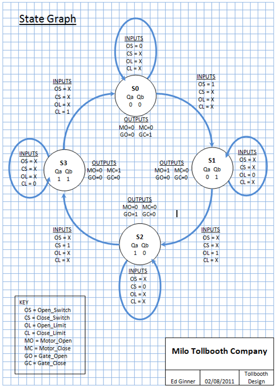
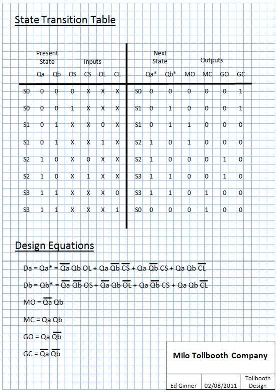
The inputs are OS(Open Switch), CS(Close Switch), OL(Open Limit), and CL(closed Limit). The Outputs are MO(Motor Open), MC(Motor Close), GO(Gate Open), and GC(Gate Closed). The inputs determine the state of the machine. The outputs are activated by the inputs which send the output a signal to open or close the motor or to turn on a LED. The state variables are Qa*/Da and Qb*/Db. They are outputs of the flip flops and their values identify which state the machine is in.
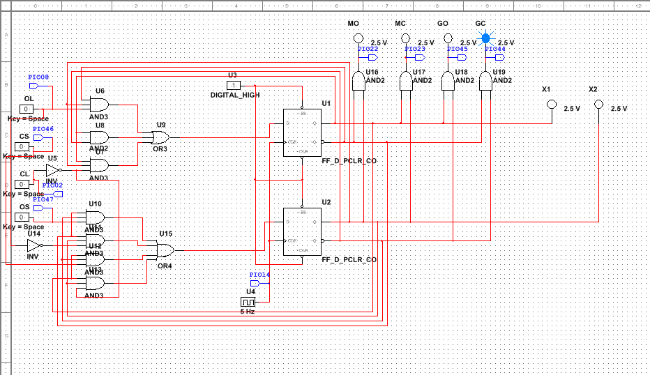
3. MultiSim (PLD Mode):
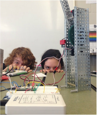
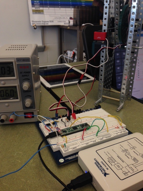
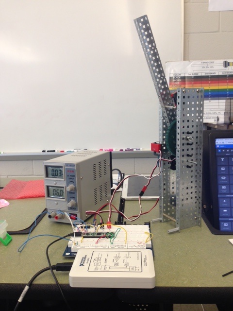
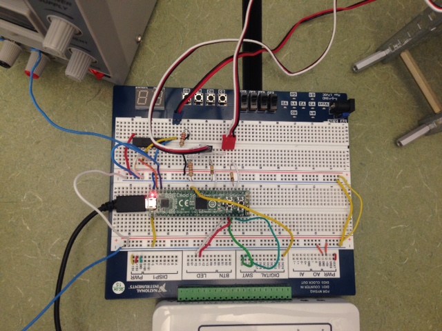
4. VEX
|
|
|
5. Conclusion:
Dear Mrs. Ziglejeva,
This past week in Digital Electronics, Logan and I had to build a tollbooth state machine out of parts and in MultiSim. We then had to transfer the program to the board which made the tollbooth operate. At first I copied down the state graph and transition table. Then I took the time to understand what was going on in the graph/table. Logan started building the tollbooth out of the VEXparts while I started to build the working simulation in MultiSim. To build it on MultiSim I need to understand the inputs of the JK flip flops and the outputs of the JK flip flops; these came for the six simplified logic expressions. I also had to understand what would make the tollbooth work. Starting out the gate closed LED would be on. I would switch on the open switch and the motor would open. It would then hit the open limit. After the open limit I would activate the close switch which would turn on the motor close. The close limit would then turn on and all the states would then be completed. In the building on the tollbooth we had to place the motor so i would turn a gear and allow the arm of the tollbooth to go up and down. The open limit was placed at the top where the arm could hit it and signal it that it was open. At the bottom there was a close limit that the arm would hit and signal that the gate was closed.Logan and I both wired the board. It was a little complicated at first but we figured it out. The only mistakes we made were with the board. We had our motor wired backwards and we did not ground the SN754410 chip so our board was not working. Also our open limit switch was not over enough so that the arm would hit it. All we had to do was adjust it so that the state could be complete. Our toll booth successfully went through all the states after we made our changes and resent the program to the board.
From this project what I learned about schematics is that at first it looks very complicated and tricky but if you take your time and trace all the lines you will be successful in the actual wiring. You have to be very careful that you connect all the correct components to the right place and that you do not forgot any connections. Reading schematics is a lot easier now than it was in the beginning of the year because I have had a lot more exposure to reading the diagrams and understanding what the components and connections do.
What I would do differently next time is try and understand the schematics diagram more first then just copying the picture because I forgot to ground the chip. If I understood the diagram first I wouldn't have missed the ground wires and I would have saved my group some time by trying to figure out why is was not working. Also I would of preferred to help Logan more with the making of the tollbooth with the Vex components so I had more of an understanding.
Why does the SN754410 chip need to be grounded on two inputs and what kind of chip was it?
