Sixty Second Timer
1. Project Overview:
|
The purpose of the sixty second timer is to design, build, and simulate a digital circuit that counts from 0-59 on two seven segment displays. This circuit also had two control inputs and two output dispays. The Clock signal contols the count rate at 1 second by having it at 1Hz. The Reset signal resets and holds the count at 0. The clock loops at 59. The circuit had to use a synchronous 74LS163 MSI counter for the ones-unit and an asynchronous JK SSI logic gate for the tens-unit. This circuit is a typical sixty second timer.
|
2. PLD Circuit:
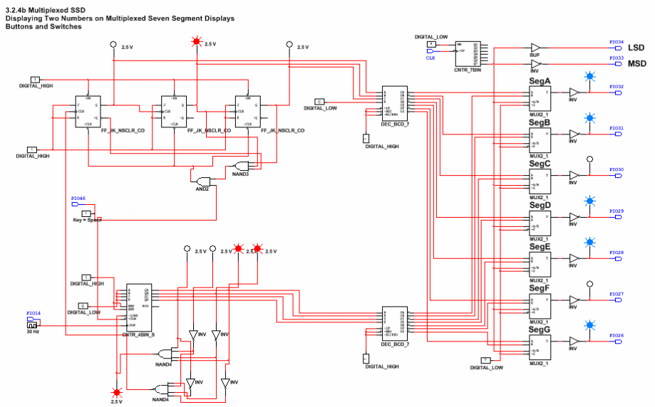
The circuit had to use a synchronous 74LS163 MSI counter for the ones-unit to count up from 0 to 9. The clock at 1 Hz controls this bottom circuit at one second intervals. The bottom circuits output clocks the top circuit which is three JK flip-flops. The top circuit is designed to count up from 0 to 5. When the bottom circuit reaches a 9, 1001, the top circuit will advance by one. Once the circuit reaches 59 it loops and starts over. There is a reset button installed so at any moment the circuit can be reset back to 0. The circuit is created on PLD mode so then it is uploaded onto the board and displayed on seven-segment displays to show the count from 0-59.
3. Conclusion:
-The difference between synchronous and asynchronous circuits is that synchronous counters do not have a ripple effect and they are faster at simultaneous clocking. Asynchronous counters require less logic and can only start at 0 and count up. Synchronous counters the flip flops are clocked simultaneously while in asynchronous the output of the first flip flop clocks the next flip flop.
-The difference between '163 and '169 is that the '163 had a synchronous load and clear so you do not have to do the count plus one, the last numbered wired is the number that shows. '193 has an asynchronous load and clear so you have to do the count plus one. '163 can only count up while '193 can count up and down. Also '193 has separate clock inputs for up and down counting.
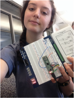
-First I pulled up the Multiplexer document on PLD so I could start building my circuits. I started first on the ones place. For the ones place I used a synchronous 74LS163 counter, CNTR_4BIN_S. I connected the 4 inputs to low/ground so my count would start at 0. I then connected the ENP and ENT inputs to high/power. The load input was wired to a LED and I inserted a 1Hz clock and connected it to the CLK input. I then connected my outputs A-D on the CNTR_4BIN_S to the inputs A-D on the DEC_BCD_7. I inserted a NAND4 gate and 4 LED's. The furthest left LED I connected to the MSB, D. I also connected an input of the NAND4 to D. I then did this with C, B, and A with the LED's and NAND4 inputs. Since I wanted to count from 0-9 I placed two inverters on the wires leading from the NAND4 inputs to B and C so it would read 1001, 9 and reset back to 0. The '163 is a synchronous load so you do not need the count plus one. I then started on my top circuit, the tens place. For this I used 3 asynchronous JK flip flops, FF_JK_NSCLR_CO. I added another NAND4 gate at the bottom of my lower circuit and added two inverters so it would detect a 0 and count the top circuit (tens place) up one. I connected the output of the bottom NAND4 to the clock of the first JK flip flop. I then connected the Q to the negative edge clocks so it would count up. I attached each J and K input to high/power. I also attached a LED to each Q so I could see the proper count. I connected the furthest right, the MSB, Q to the input C on the DEC_BCD_7. I connected the middle Q to B and the furthest left, LSB, to A. I inserted a NAND 3 gate and connected the inputs to ~Q on the LSB, furthest left, Q in the middle, and Q on the MSB, furthest right. I did this so it would detect a 6 and reset it to a 0. I needed a reset switch so I placed a AND2 gate in between the two circuits. I connected one input to a switch and to the clear of the '163. I connected the other input to the NAND3 output. I then connected the output of the AND2 to the 3 clears on the JK flip flops so it would reset to 0. I added to input pins. A pin14 for the clock and a pin46 to the switch. I verified my circuit worked by running it and checking the LED's. After it worked properly, I built it on a board. I connected the clock, DIO1 to pin 14, a button to pin 46, connected pins 26-32 to G-A, starting with G for 26, for the seven segment displays. I also powered pin 24 and grounded 25, and set pin 33 to the ones display DIS0 and 34 to the tens display DIS1. I uploaded the circuit to the board and powered the NImyDAQ.
-Yes my classmates created something different. While Logan and I had the same circuit Frank and I did not. While I connected a second NAND4 input below my first NAND4 input with only 2 extra inverters for the ones place/'163 as the clock to the JK flip flops/ tens place, Frank added a NAND4 above the '163 seperatly and used 4 inverters as the clock for the JK flip flops. Frank also had 4 JK flipflops while I only had 3.
-The difference between '163 and '169 is that the '163 had a synchronous load and clear so you do not have to do the count plus one, the last numbered wired is the number that shows. '193 has an asynchronous load and clear so you have to do the count plus one. '163 can only count up while '193 can count up and down. Also '193 has separate clock inputs for up and down counting.
-First I pulled up the Multiplexer document on PLD so I could start building my circuits. I started first on the ones place. For the ones place I used a synchronous 74LS163 counter, CNTR_4BIN_S. I connected the 4 inputs to low/ground so my count would start at 0. I then connected the ENP and ENT inputs to high/power. The load input was wired to a LED and I inserted a 1Hz clock and connected it to the CLK input. I then connected my outputs A-D on the CNTR_4BIN_S to the inputs A-D on the DEC_BCD_7. I inserted a NAND4 gate and 4 LED's. The furthest left LED I connected to the MSB, D. I also connected an input of the NAND4 to D. I then did this with C, B, and A with the LED's and NAND4 inputs. Since I wanted to count from 0-9 I placed two inverters on the wires leading from the NAND4 inputs to B and C so it would read 1001, 9 and reset back to 0. The '163 is a synchronous load so you do not need the count plus one. I then started on my top circuit, the tens place. For this I used 3 asynchronous JK flip flops, FF_JK_NSCLR_CO. I added another NAND4 gate at the bottom of my lower circuit and added two inverters so it would detect a 0 and count the top circuit (tens place) up one. I connected the output of the bottom NAND4 to the clock of the first JK flip flop. I then connected the Q to the negative edge clocks so it would count up. I attached each J and K input to high/power. I also attached a LED to each Q so I could see the proper count. I connected the furthest right, the MSB, Q to the input C on the DEC_BCD_7. I connected the middle Q to B and the furthest left, LSB, to A. I inserted a NAND 3 gate and connected the inputs to ~Q on the LSB, furthest left, Q in the middle, and Q on the MSB, furthest right. I did this so it would detect a 6 and reset it to a 0. I needed a reset switch so I placed a AND2 gate in between the two circuits. I connected one input to a switch and to the clear of the '163. I connected the other input to the NAND3 output. I then connected the output of the AND2 to the 3 clears on the JK flip flops so it would reset to 0. I added to input pins. A pin14 for the clock and a pin46 to the switch. I verified my circuit worked by running it and checking the LED's. After it worked properly, I built it on a board. I connected the clock, DIO1 to pin 14, a button to pin 46, connected pins 26-32 to G-A, starting with G for 26, for the seven segment displays. I also powered pin 24 and grounded 25, and set pin 33 to the ones display DIS0 and 34 to the tens display DIS1. I uploaded the circuit to the board and powered the NImyDAQ.
-Yes my classmates created something different. While Logan and I had the same circuit Frank and I did not. While I connected a second NAND4 input below my first NAND4 input with only 2 extra inverters for the ones place/'163 as the clock to the JK flip flops/ tens place, Frank added a NAND4 above the '163 seperatly and used 4 inverters as the clock for the JK flip flops. Frank also had 4 JK flipflops while I only had 3.
