Majority Vote
1. Project Overview:
The purpose of project 2.1.1 Majority Vote is to design an electronic voting machine. This machines will allow four board members to cast their ballots and will display the pass/fail status of each of their decisions. For a decision to be a yes, the majority of the board members must vote yes and in the event of a tie, the presidents vote is used to break the tie. In this project one will use AND, OR, and Inverter logic gates to design, simulate, and build a majority voting machine. One must use two-input gates only as a constraint and one must also have a simplified and un-simplified circuit and expression.
2. Problem Conception via Truth Table & Un-simplified Expression:
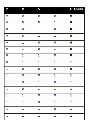
A truth table is used to show how a logic circuit responds to various combinations of inputs. If there is a number one, that shows that the input is true or if the switch is on or is a yes. If there is a number zero, that shows that the input is false or if the switch is off or is a no.
This truth table has 4 different inputs. There is 16 rows because 2 to the 4th power is 16. A logic design with N inputs will have 2^N input combinations. In order for the decision to be a yes (1), then the majority of the board members must vote yes (1).
In the case of a tie, this truth table shows that if the president (P) votes yes (1) with any other board member, then the decision will be a yes (1). The decision will be a no (0), if only 1 member votes yes (1), or in the case of a tie, the president votes no (0).
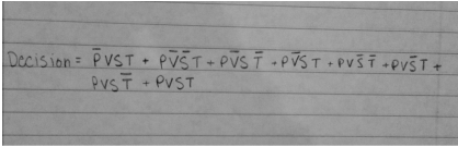
This is the un-simplified logic expression that came out of the truth table above. I arrived at this answer by looking for every 1 in the decision column. A 1 indicates a yes, meaning that the decision will pass. If there is a 0, the decision will not pass. A logic expression just shows when the decision will generate a 1/ passing vote. My logic expression is in sum of products (SOP) form because it is easier to derive from a truth table and it is easier to derive a Boolean Algebra Simplification from. To find your minterms, you look for a 1 in the decision column ad then look at the corresponding row. If there is a 0 it is not that input; if there is a 1 it is that input. In this case all 4 inputs multiplied (AND gate) creates your minterm in SOP and creates an output of 1. All the minterms added together (OR gate) becomes your un-simplified logic expression.
3. Un-Simplified Circuit:
This is the un-simplified AOI logic circuit I created for the majority vote voting machine. This circuit was created only using two-input gates and it follows the logic expression shown above.
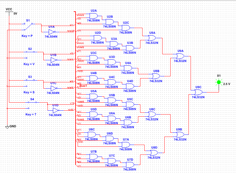
This un-simplified circuit is created in bus form to allow the creating of the circuit to be easier. To create the circuit I used 4 invertor gates (74LS04), 24 AND gates (74LS08), and 7 OR gates (74LS32). To build this circuit on a breadboard one would need 1 invertor chip (74LS04), 6 AND chips (74LS08), and 2 OR chips (74LS32). An invertor changes the input to not the input, an AND gate multiplies two inputs, and an OR gate adds two inputs.
4. Boolean Algebra Simplification:
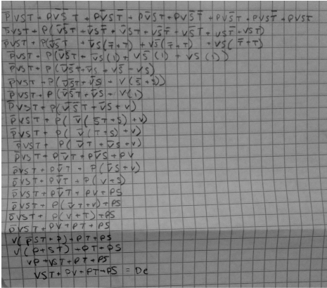
The un-simplified expression in the first line was simplified down to the expression in the last line by Boolean Algebra. I used the different theorems and laws to simplify the large expression to the shorter expression which is much easier and cheaper to work with.
The final expression: Decision= VST + PV+ PT+ PS
The final expression: Decision= VST + PV+ PT+ PS
5. Simplified Circuit:
This is the simplified AOI logic circuit I created for the majority vote voting machine. This circuit was created only using two-input gates and it follows the logic expression shown above. This creates the same output as the un-simplified circuit but it is much easier to create.
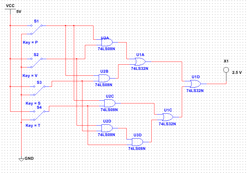
This simplified circuit is not created in bus form because there was not a lot of gates involved. To create the circuit I used no invertor gates (74LS04), 5 AND gates (74LS08), and 3 OR gates (74LS32). To build this circuit on a breadboard one would need no invertor chip (74LS04), 2 AND chips (74LS08), and 1 OR chip (74LS32). I figured this out because each chip can conduct 4 actions. Because there are 5 AND gates, I will need two AND chips. Because there are 3 OR gates, I will need one OR chip.
This simplified circuit contains 4 less invertor gates, 19 less AND gates, and 4 less OR gates. This simplified circuit will also contain less wires and less space. One would build a simplified circuit over an un-simplified circuit because it will take less materials which makes it less expensive, it will be much quicker to create, the current will take less time to transfer from the beginning to the end, and problems will be much easier to see and correct.
This simplified circuit contains 4 less invertor gates, 19 less AND gates, and 4 less OR gates. This simplified circuit will also contain less wires and less space. One would build a simplified circuit over an un-simplified circuit because it will take less materials which makes it less expensive, it will be much quicker to create, the current will take less time to transfer from the beginning to the end, and problems will be much easier to see and correct.
6. Bill of Materials:
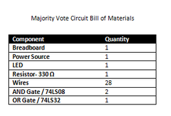
This a bill of materials that lists all the materials that I needed to make my circuit for the majority vote project. On the left is each component utilized and on the left is the quantity of the component. I used one breadboard, one LED, one power source, one 330 ohm resistor, one OR gate, two AND gates, and 28 wires.
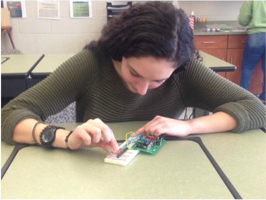
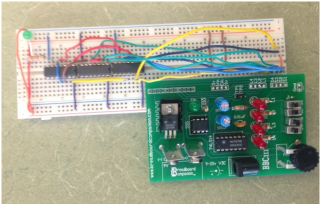
7. Bread-boarding:
|
|
|
|
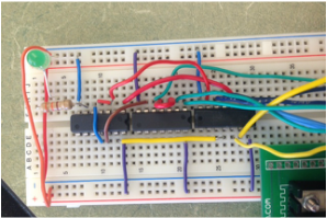
This is the working prototype of my simplified circuit. S1 represents P, S2 represents V, S3 represents S, and S4 represents T.
|
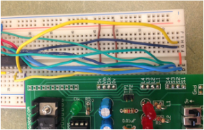
This is showing the right portion of my breadboard. The power source is grounded and powered. S1 has to be connected to the other side of the circuit with a wire so I can utilize S1 more times. The light blue wires connect S1 and S2 to an AND gate. The dark blue wires connect S1 and S3 to and AND gate. The yellow wires connect S1 and S4 to an AND gate. The green wires connect S2, S3, and S4 to an AND gate.
|
Each gate has to be grounded and powered. The red and orange wired connect the left side to the right side. The right and middle gates are AND gates. The left gate is an OR gate. The LED shows if the vote passes or fails and the resistor is used to limit the current to the LED. The LED is grounded.
|
My breadboarding experience went very well. The first time I tired my breadboard, it was not successful; I went back and looked at my board and saw that one of the wires was not completely in its slot. I pushed the wire in and then my breadboard was successful. During my experience I learned that organization and detail are very important. You need to make sure that your wires are not all over the place and that you have a systematic approach so you don't forget or do something twice. One needs to insure that they ground and power the chips and the power source and that they do it correctly. One also has to be patient and take things slowly so they complete their circuit successfully.
8. Final Project Conclusion:
This project was very informational on how to derive, design, simply, and construct a circuit with a problem statement. After we read and understood the problem statement we had to create a truth table, un-simplified logic expression, and an un-simplified circuit. From there we had to simplify the logic expression with Boolean algebra.The Boolean algebra was immensely helpful to simplify the expression and therefor create a more simple simplified circuit. Then we created the simplified circuit and then made it on the breadboard. Working through this project my skills on wiring, Boolean algebra, and creating circuits improve. This project showed the importance of taking a long expression and simplifying it to make things easier and quicker. Overall this project was a great way to display circuits, logic expression, and Boolean algebra in a real world sense and a very effective way to learn the technical side of it.
