Random Number Generator Project- February 2015
1. Define a problem-
|
|
|
2. Generate concepts-
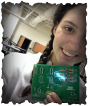
This project was the assembling and testing of a random number generator kit that randomly displays a number between one and six in the patterns typically seen on a board game die. During this project we soldered the components of the kit together to create our random umber generator and make sure it was working correctly. The main goals were to correctly solder and to test the random number generator to see if we assembled the circuit correctly and accurately.
3. Develop a solution-
4. Construct and test prototype-
|
(see signature from section 3)
|
5. Evaluate the solution-
Conclusion questions:
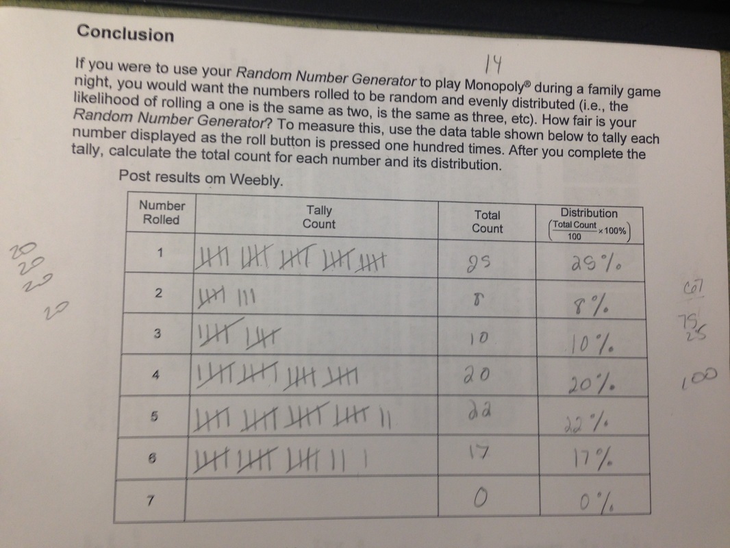
1) The numbers on my random number generator were not evenly distributed, they ranged from 8% to 25%. I do not think my random number generator was fair because you had a 17% more likely chance to get a 1 then to get a 2. Also number 7 was never picked because the numbers generated were based off a cube; 1-6. Number 2 only came up approximately 8% and number 3 was only 10%, meanwhile number 1 came up approximately 25% and number 5 was 22%.
2) Admiral Grace Hopper coined the term debugging in 1945. While Hopper was working on a computer at Harvard University, she stumbled upon a moth in the relay, therefor impending the operation; she stated that they were debugging the system.
Reflection:
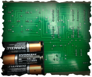
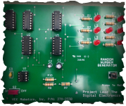
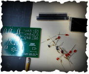
We started this project with the random number generator kit. This kit contained seven 180Ω resistors, one 1.2kΩ resistor, one 10kΩ resistor, one 18kΩ resistor, seven red LEDs, one 100µf capacitor, one .47µf capacitor, one .01µf capacitor, one N.O. pushbutton switch, one SPST switch, a 555 timer, five integrated circuits, a printed circuit board, and a battery holder. We opened the kit and soldered the components in their proper places. First the resistors, then the LEDs, the capacitors, the switches, the 555 switch, the integrated circuits, then finally the battery holder. During soldering we had to make sure that the component was flush to the board and that we created a nice ‘Hershey kiss’- not too much or too little solder. After we soldered we had to clip the ends off flush to the board. Once we assembled everything, we placed the 3 batteries in and tested the circuit, If it worked, which mine did, we tested it 100 times to get results from our random number generator. As I worked on my project, I encountered some small problems. On a few components I did not solder flush to the board so I had to reheat the solder and push the component flush. On some soldering tries I came close to burning the solder and or myself. During my project there were no large problems to address though. I really enjoyed this project and how it taught me how to solder. It made me feel accomplished once I finished it and saw that I had a properly functioning random number generator.
We started this project with the random number generator kit. This kit contained seven 180Ω resistors, one 1.2kΩ resistor, one 10kΩ resistor, one 18kΩ resistor, seven red LEDs, one 100µf capacitor, one .47µf capacitor, one .01µf capacitor, one N.O. pushbutton switch, one SPST switch, a 555 timer, five integrated circuits, a printed circuit board, and a battery holder. We opened the kit and soldered the components in their proper places. First the resistors, then the LEDs, the capacitors, the switches, the 555 switch, the integrated circuits, then finally the battery holder. During soldering we had to make sure that the component was flush to the board and that we created a nice ‘Hershey kiss’- not too much or too little solder. After we soldered we had to clip the ends off flush to the board. Once we assembled everything, we placed the 3 batteries in and tested the circuit, If it worked, which mine did, we tested it 100 times to get results from our random number generator. As I worked on my project, I encountered some small problems. On a few components I did not solder flush to the board so I had to reheat the solder and push the component flush. On some soldering tries I came close to burning the solder and or myself. During my project there were no large problems to address though. I really enjoyed this project and how it taught me how to solder. It made me feel accomplished once I finished it and saw that I had a properly functioning random number generator.
6. Present the solution-
(see signature from section 3)
7. Required assistance-
(see picture from section 3)
