Deli Counter Display
1. Project Overview
For the Deli Counter Display I had to design, simulate, and build a digital circuit that displays the count from 00 to 80 on two seven segment displays, stops at 80, and ceases whenever the button is released. The design had to have two inputs, next and reset. The next signal comes from a push-button switch that when pressed would advance the count by one. The reset signal comes from a push-button switch that resets the count to 00 when released. When the display reaches 80 the count will cease. This is the type of display that one would commonly see at a deli counter.
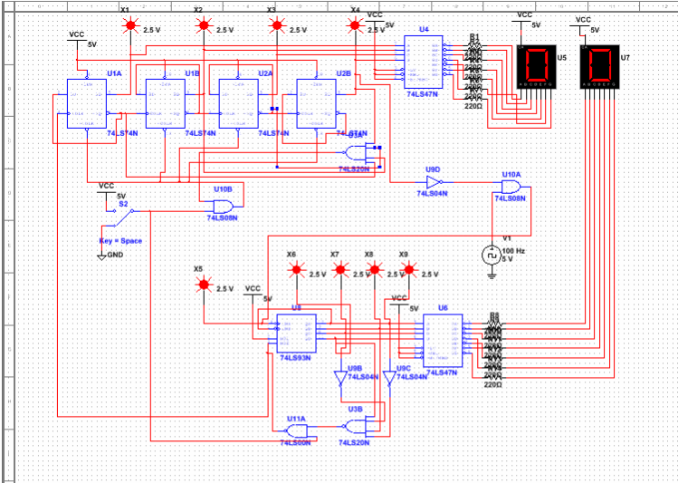
2. MultiSim Circuit
3. PLD Circuit
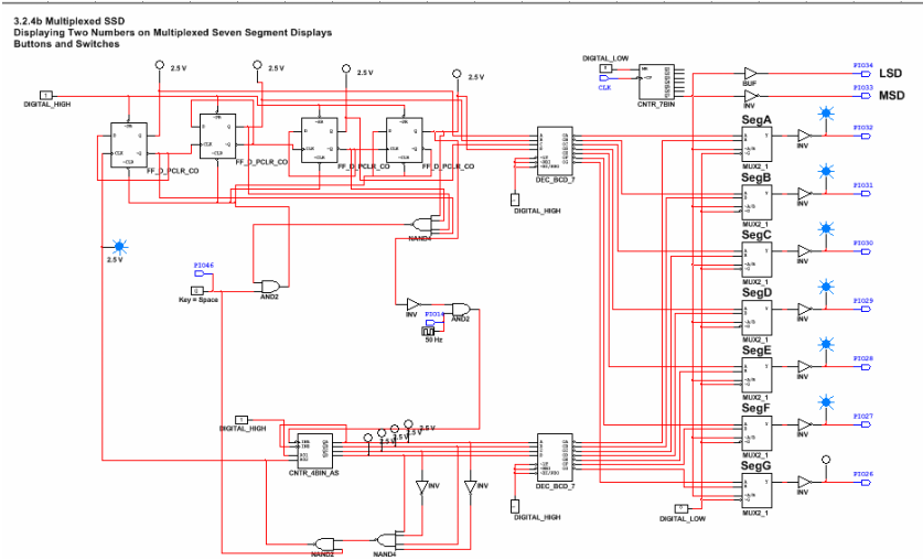
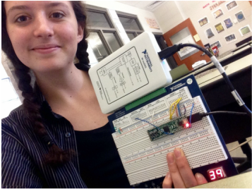
PLD mode is programmable logic devise mode and it is the integration between the stimulation and hardware implementation. In PLD mode, one designs there circuit, assign the input and output pins, and upload the process to the board to simulate the circuit. Design mode is the design and simulation on multisim. In design mode you do not transfer the circuit onto the board, you test it on multisim. In PLD mode there are input and output connectors that you have to designate inputs (switches/buttons/clock) and outputs (7 segment display) while in Desgin mode the input and outputs are already designated in the program. In PLD mode, you upload and run a circuit on a breadboard. To run the circuit you have to upload your circuit to the board via a USB and power the board with a NI myDAQ. The circuit is uploaded to the CMODS6 chip and the program should run.
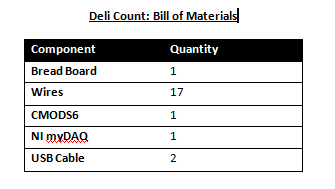
4. Bill of Materials
5. Final Project Conclusion
A SSI circuit is small scale integration. SSI gates are very basic gates that must be wired manually. They require more time and effort and take up more space and wires. An example is a flip flop.
A MSI circuit is medium scale integration. MSI gates are a little more complex. A MSI gate does the work of 4 flip flops in one gate. They consume less space and wires and it is quicker and easier to wire. An example is a 74LS93 chip.
The limitations of the MSI circuit, 74LS93, I created was that it can only count up and that it can only start at 0.
The meaning of the ripple effect is a small amount of propagation delay between flip flops that causes a random number to be displayed on the seven segment display for a short period of time.
Set up of my design: When I press B0, pushbutton, the next signal travels to the clock input, pin 14 on the 74LS93 chip. This makes the two seven segment displays count up from 00 to 80. When I release B0, pushbutton, the reset signal travels to the clock input. This resets the two seven segment displays to 00. Pins 26-32 on the 74LS93 chip are connected to A-G to light up the LEDs on the seven segment timer. The pushbutton, B0, is connected to pin 46. Also, each seven segment timer is wired to pin 33 and 34. The clock is wired to pin 14, as always. For my 'ones place', the MSI citcuit, is wired to detect a 10 and reset at 0 so it counts 0-9. By placing an inverter on the MSB and the second LSB, this allows the chip to detect a 10 and reset the count to 0. The output of the MSI has a four input NAND gate followed by another NAND gate, the other input coming form the switch that acts as the clock to the SSI circuit to count up one digit. This process continues until the number 80. At this point, the suspend count, a clock and an inverted '8' from the SSI circuit, to an AND gate detects the number 8 suspends the count until the button B0 is released and the circuit is reset. The SSI circuit it wired to count up from 0-8.
Yes the majority of my classmates created circuits that differed from mine. For my reset switch I used an AND gate with an input from the NAND4 and from the switch with the output from my 'ones place' generator. My classmate used an AND gate with an input from the NAND4 and from an inverted switch with the output from their 'ones place' generator.
